Quick Tour
Adjusting the images
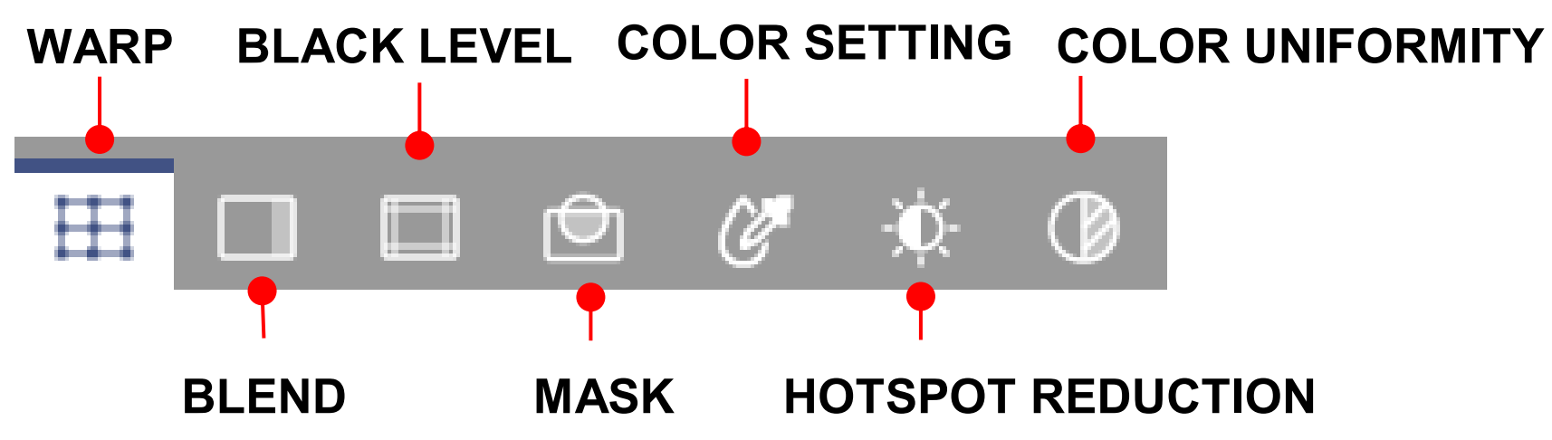
This tool offers three ways to adjust the images – warping, blending, masking, black level and HSG. To switch between the functions, use the function tabs at the right top corner of the main workspace.
I. Warping the images
Image warping is used to make an image look visually correct when it is projected onto a non-planar screen.
Use the settings on the WARP page to change the image shape.
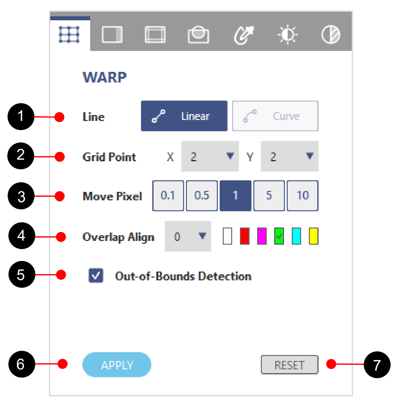
Function tab – WARP
| No. | Function | Description |
| 1 | Line – Linear – Curve |
Set the line warping style. Moving the point results in the lines changing the shape linearly. Moving the point causes the line shape changes in nonlinear fashion, not available at 2×2 grid points. |
| 2 | Grid Point | Set the number of grids on the screen.(support to 65×33) |
| 3 | Move Pixel | Set the pixel movement of the control point. |
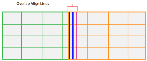
| 4 | Overlap Align | Set the width and color of line for alignment. |
| 5 | Out-of-Bounds Detection |
A checkbox function to avoid the point movement is too extreme. |
| 6 | Apply | Apply the warping adjustment. |
| 7 | Reset | Clear the warp settings. |
Warping an image
Complete following steps to warp an image.
- Choose a projector by clicking on its layout frame or choose it from the Layer tab.
- At the Test Pattern toolbar, select the grid test pattern on projection.
- At the Line field, select the line warping style from Liner or Curve according to the screen type.
Linear adjustment
Curve adjustment
- At the Grid Point field, select the number of grids on the screen. Start with a minimal number of grids (2×2) and gradually increase the number when adjusting. Decreasing the grid number during adjustment will erase some of points setting.
- At the Test Pattern toolbar, click the ALIGN button to align the test pattern lines with the grid points.
- At the Move Pixel field, adjust the slider or enter a value to set the number of pixels that the selected point moves each time. Shortcuts: Press Ctrl + Up arrow to increase the pixels, or Ctrl + Down arrow to decrease the pixels.
- Select the points you want to move. The chosen ones turn to orange.
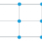
Select a single point
– Click the point or use the W, A, S, D keys to select a point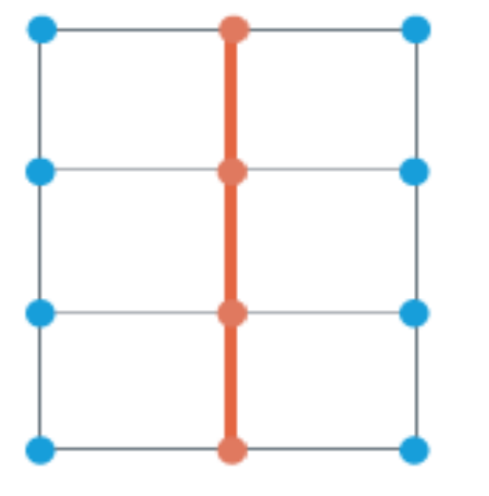
Select all points on a line
– Place the mouse cursor anywhere on the line, and press Ctrl + V to choose a vertical line, or Ctrl + H for a horizontal line.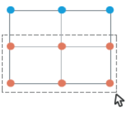
Select all points inside a region
– Click and drag the cursor to select a region, and release the mouse to select all the points inside. - To warp the image, click and drag the grid points to move them, or use the keyboard arrow keys.
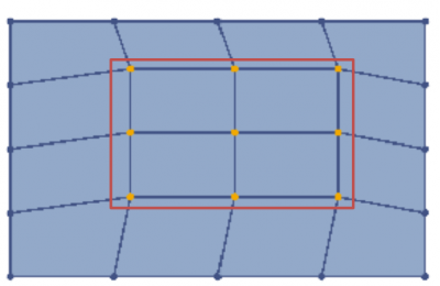
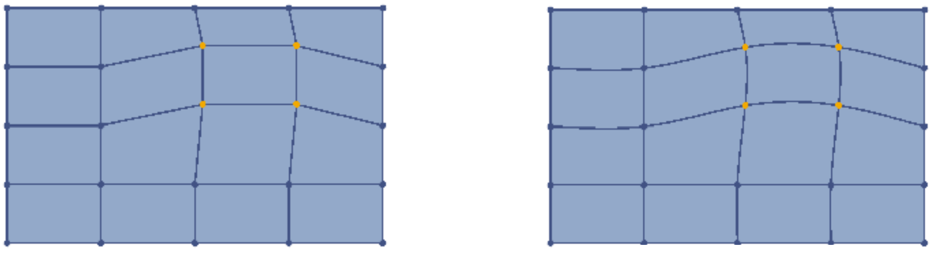
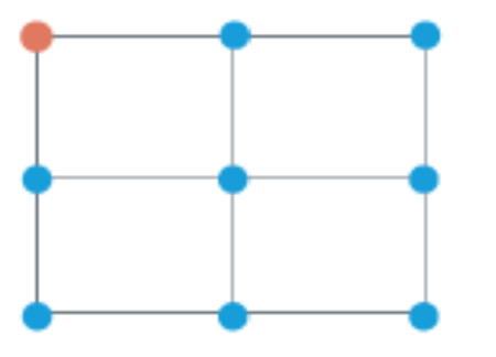
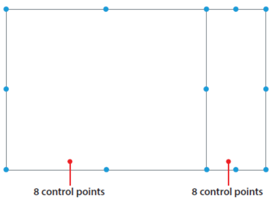
Note: To make the warp easier, start with the outer area of the screen, and then move to the center area. As shown in the left image, adjust the red points first, and then move the blue ones. - Click Preview
 to see the warping of projection content, then click Preview again to return to the test pattern.
 - To Clear the warp setting, as the function tab, click RESET
- To save the settings to the projector memory, at the top toolbar, click Save. The setting is saved to the Save Location selected.
Warping for image blending
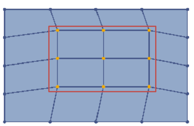
When performing edge blending on two adjacent images, slightly change the shape of the overlapped area helps align the two images more precisely. In the example below, two projectors are placed side by side, and warping the overlapped edges of the images helps achieve a better edge alignment.
- For better alignment manually, set two test patterns with the same number of grid lines, but different grid line color.
- Adjust the warp control points for grid line alignment on overlapped area.
For example, point A of left projection is moved down to align the top line of right projection, and point B of right projection is movd down to align the bottom line of left projection.
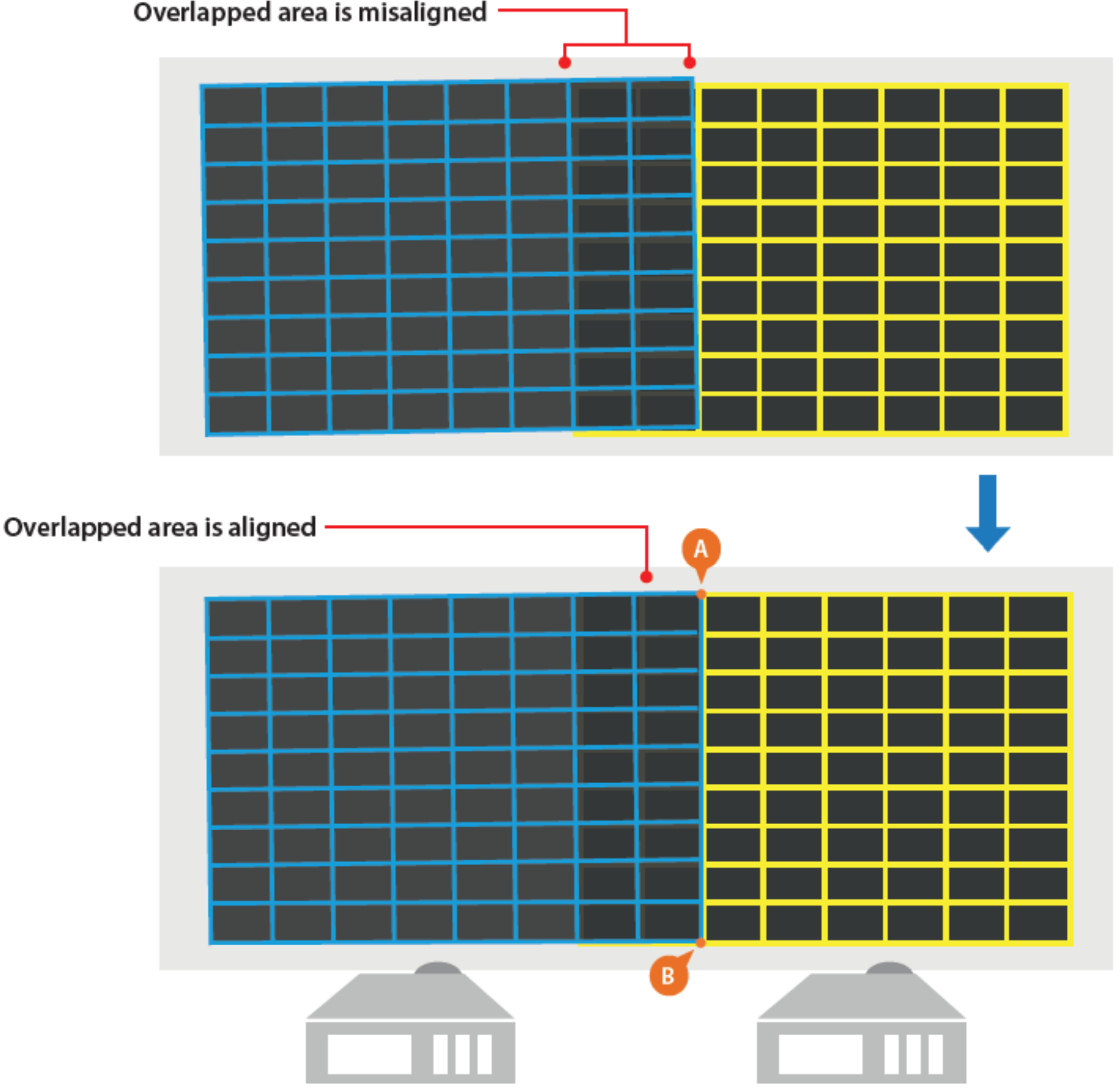
Warp for edge blending
Note: To achieve the best result, it is suggested warping the image which is slightly larger. Also, adhere to
the rule of adjusting the outer points first, and then moving to the inner points.
II. Blending the images
Image blending is an image process to merge two or more partial images to a complete image. Use the
settings on the BLENDING page to blend the images.
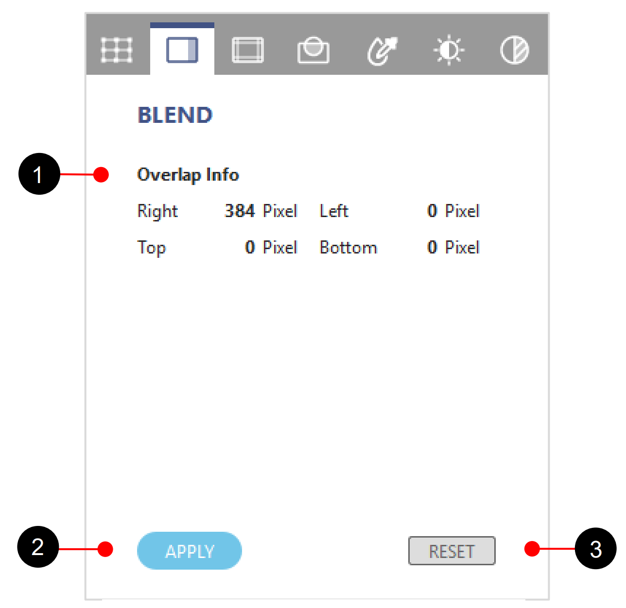
Function tab – BLEND
| No. | Function | Description |
| 1 | Overlap Information | Top/Bottom/Left/Right Overlap blending width |
| 2 | Apply | Enable the blending data. |
| 3 | Reset | Reset blending width to default setting. |
Complete following steps to blend two adjacent image.
- Choose a projector by clicking on its layout frame or choose one from the Layer tab. After being selected, the projector frame turns to light blue.
- At the Test Pattern toolbar, set up the grid test patterns for the projectors. It’s suggested setting the two test pattern with the same number of lines, but different line color.
- At the WARP tab, set up the line number and color of Overlap Align for each projector. On the overlapped area, Overlap Align draws marking lines as guides to help align the edges.
Align two adjacent images
- Select a projector, and click on the overlapped edge.
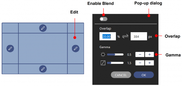
Setup the blend edge
- At the pop-up dialog, set up the blending edge
- Switch on the Enable toggle button to enable the blending effect.
- At the Overlap field, set the overlap width for blending by image percentage or pixel value. The percentage and pixel value is based on the projection resolution.
- Adjust the Gamma setting to change the inflection and gradient of gamma curve.
- Click OK to apply the blending setting to the edge.
- Enable the blending effect, the selected edge is applied with a gradient effect.
- Click Preview To view the results of the current adjustment, at the top toolbar, click Preview to project an image. Click Preview again to return to the test pattern.
- Repeat step 4 to 8 on the other projector to setup its overlapped edge.
- To Clear the warp setting of the chosen projector, at the function tab, click RESET.
- To save the settings to the projector memory, at the top toolbar, click Save. The setting is saved to the Save Location selected.


III. Black Level
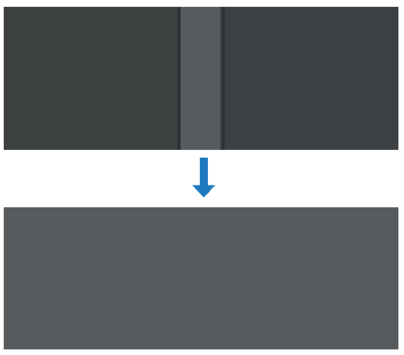
After blending two images, the overlapped area may appear brighter than the rest of the image when projecting dark images.
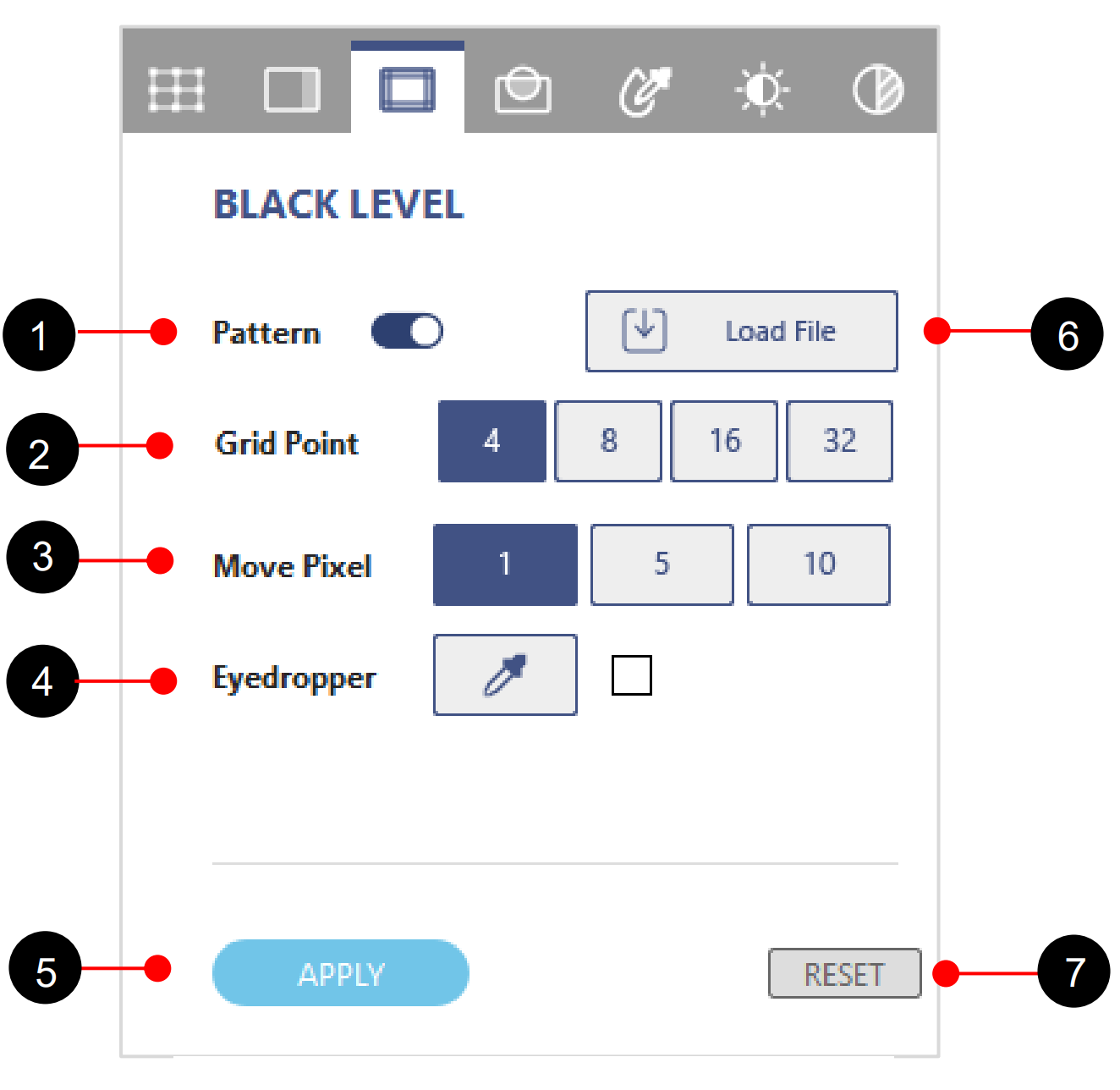
Function tab – BLACK
| No. | Function | Description |
| 1 | Pattern | Enable the black level effect. |
| 2 | Grid Point | The grid points control the adjustment of black level area for better edge alignment of overlap area, up to 32 points for each black level area. |
| 3 | Move Pixel | Set the pixel movement of control point. |
| 4 | Eyedropper | Eyedropper mode to pick up the black level color. |
| 5 | Apply | Enable and apply black level data |
| 6 | Load File | Load the black level image file at bmp, png and jpg format. |
| 7 | Reset | Reset the black level settings. |
To uniform the color performance, adjust the color of the non-overlapped area and the black border to make them look like the same with the overlapped area.
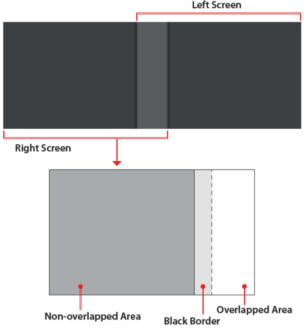
Black Level Areas
Note : Make sure that the black level adjustment is under dark field for good observation of black level variation.
Complete following steps to adjust the black level:
- Switch to the Black Level function tab. The test pattern automatically changes to the black background.
- Choose a projector by clicking on its layout frame or choose one from the Layer tab. After being selected, the projector frame turns to light blue.
- Set the Move Pixel by adjustment the slider or enter a value. The value is the pixel number
the control point moves each time when using the keyboard arrow keys. - Select the Grid Point value. The grid points control the adjustment of black level area for edge alignment with adjacent overlap area, up to 32 points adjustment for each black level area.
Grid Point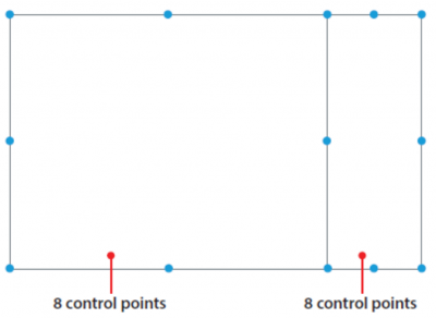
Note: Start with 4 grid point number for the adjustment and increase the points gradually. Grid Point - Set Move Pixel to control the movement for accurate alignment of adjacent black level area, user can set the value accordingly.
- Select adjustment areas using the control points. You can select two areas to adjust, one for the non-overlapped area, and one for the black border.
- Click on the point you want to move.
- Drag the selected point to change its position on the canvas, or use the keyboard arrow keys.
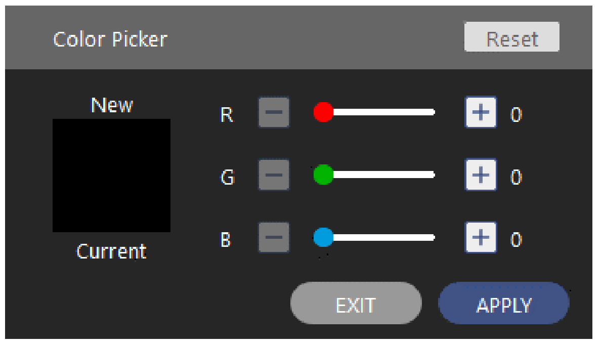
- To adjust the black level color of the selected adjustment area, click on one of the area and. The Color Picker diagram pops up.
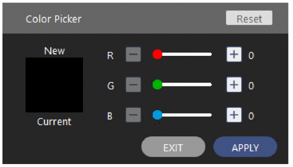
Color Picker
- Enter the RGB value or drag the slider to set the color of the selected area.
- Click APPLY on the Color Picker dialog to apply the value to the selected area.
- Repeat step 7 to 9 to adjust the color of the adjustment areas until they look like the same with the overlapped area.
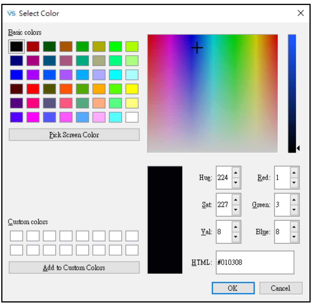
- To adjust the black level color of the selected adjustment area, click on
 to enable the eyedropper color palette and adjust the black color in Color Palette dialog.
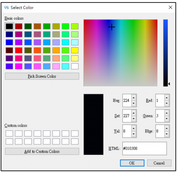
Color Eyedropper
- Enter the RGB value or pick the color from color palette to set the color of the selected area.
- Click OK on the Color Palette dialog to apply the value to the selected area.
- Repeat step 7to 13 to adjust the color of the adjustment areas until they look like the same with the overlapped area.
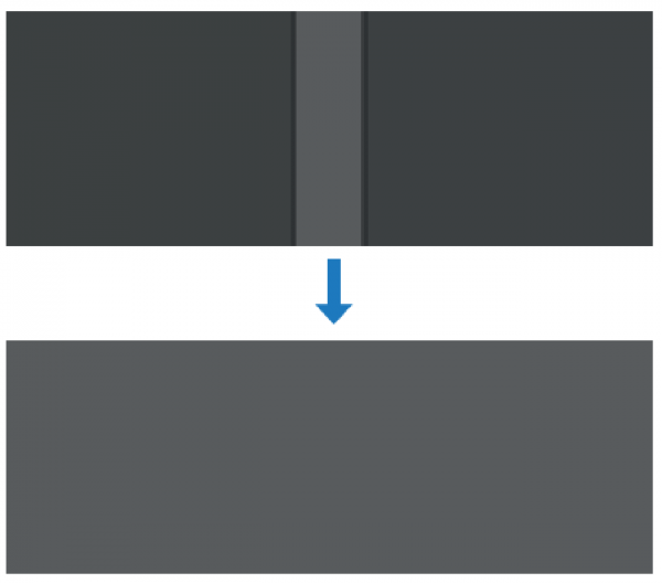
Black Level adjustment
- To clear the black level settings, at the function tab, click RESET.
- To save the setting to the projector memory, at the top toolbar, click Save. The settings is saved to the Save Location selected.
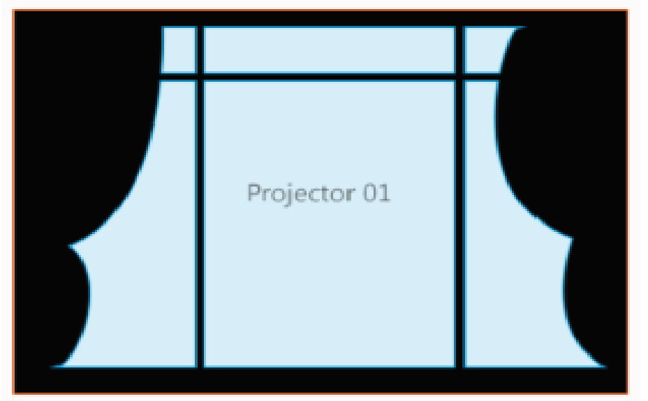
IV. Masking
Masking function allows you to mask out a part of a screen, creating a special visual effect. You can create a mask using the preset patterns, or use an image from external source.
Note: The mask function only accepts external image in BMP/JPEG/PNG format with a color greyscale of 0 (black) or 255 (white).
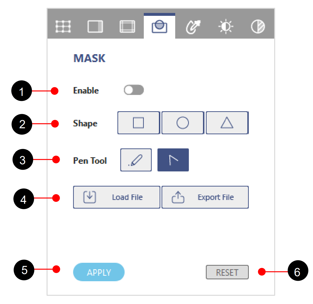
Function tab – MASK
| No. | Function | Description |
| 1 | Enable Mask | Enable the mask function. |
| 2 | Shape | Select a mask shape, Square, Circle and Triangle. |
| 3 | Pen Tool | Use pen tool to draw the mask. |
| 4 | Load/Export | Load/Export an image to mask the screen. |
| 5 | Apply | Enable and apply mask data. |
| 6 | Reset | Clear the mask on the screen. |
Creating a new mask
Complete following steps to create a new mask,
- Choose a projector by clicking on its layout frame or choose one from the Layout tab. After being selected, the projector frame turns to light blue.
- At the Test Pattern toolbar, select a background color for the chosen projector.
- Switch on the toggle button
 to enable the mask effect.
 - At the Shape field, select a shape to adjust the size and position for the mask on the screen.
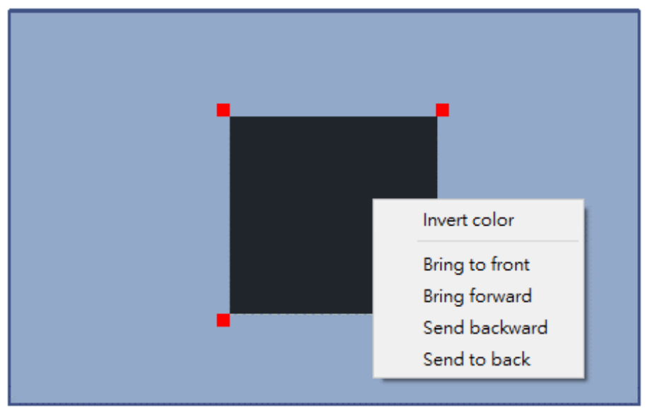
- User can right click mouse on the shape to open the Layer Setting dialog to edit the mask layers or invert the mask color.

Invert the mask and the layer setting
- To move the mask on the screen, click and drag it to the change its position.
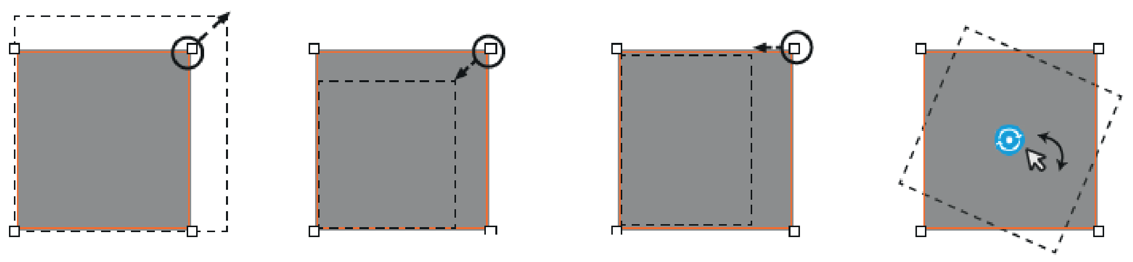
- Use the control point on the mask to change the size and shape.
- Left mouse click and drag one of the adjustment point to adjust the mask shape.
- Right mouse click to rotate the mask shape.
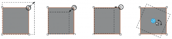
Edit the mask
- Click Preview to view the mask effect on projection, then click Preview again to return to the test pattern.
- To clear the mask on the screen, at the function tab, click RESET
- To save the settings to the projector memory, at the top toolbar, click Save or File >Save AS
Loading a mask
Complete following steps to load the image file to mask the screen.
- Check the image you are going to use, and ensure it is in the BMP/JPEG/PNG format with a color greyscale of 0(black) or 255(white)
- Choose a projector, and at the MASK function tabe, Click Load File.
- From the pop-up windows dialog, select and open a file from your computer.
- Click Preview to see the mask effect on projection, then click Preview again to return to the test pattern.
 |
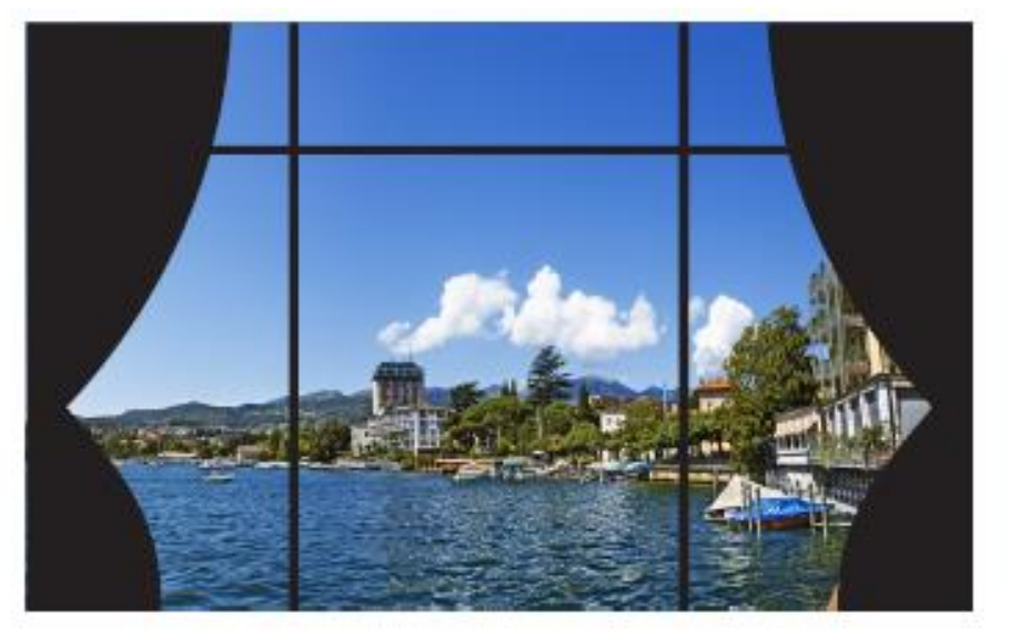 |
| Load a mask pattern | Preview a mask |
Note: The mask image does not support any modification, such as position moving, resize or rotation.
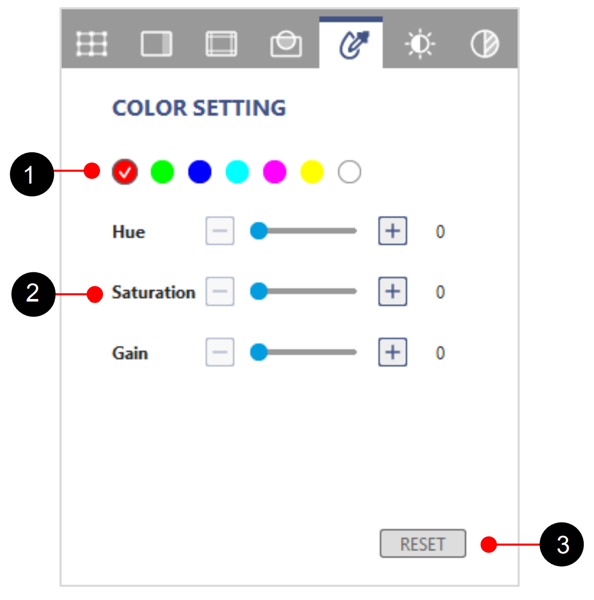
V. Projector Color Setting
Color Setting allows user to adjust Color Matching setting of projector. Change the color of a projected image by adjusting each color component in the image. You can select one of colors ad adjust the Hue, Saturation and Gain Values.
Function tab – Color Setting
| No. | Function | Description |
| 1 | Base Color | Pick up a base color to adjust the color parameters. |
| 2 | Hue/Saturation/Gain | Adjust HSG value. |
| 3 | RESET | Click to reset the HSG value to default setting. |
VI. Hotspot Reduction
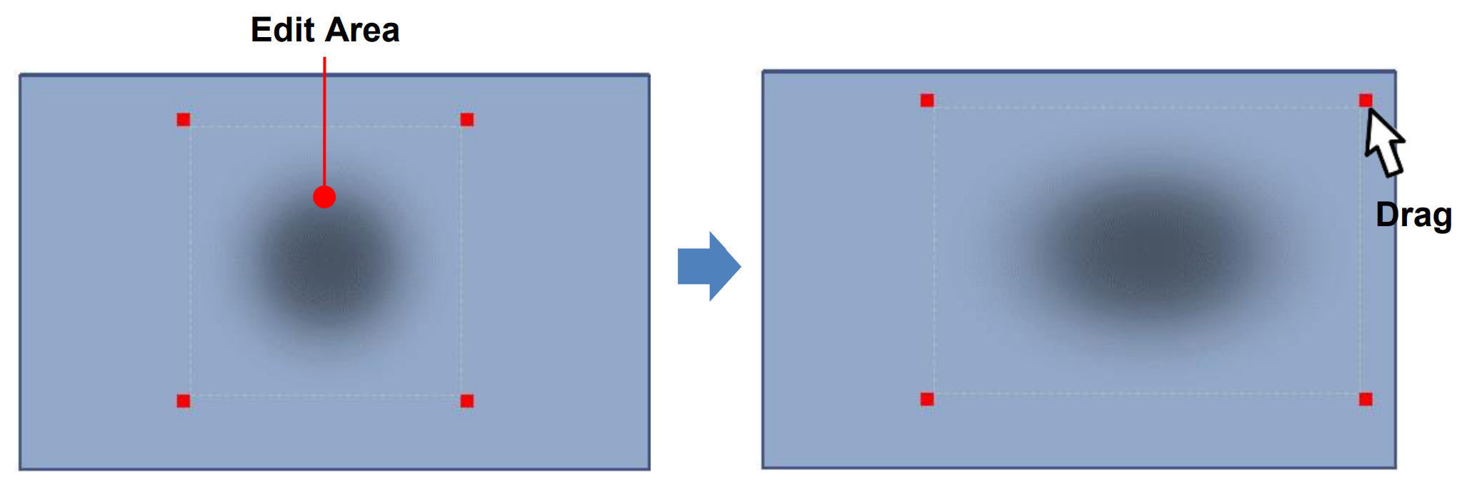
When there is a hotspot area in the projected image, you can use this function to reduce the brightness of the area to improve the overall brightness uniformity of the image.
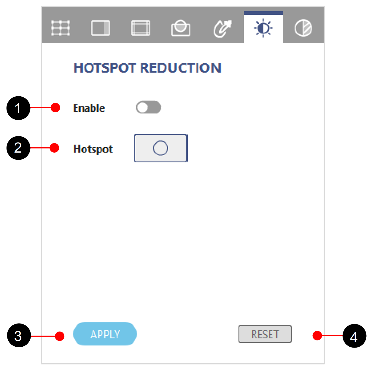
Function tab – Hotspot Reduction
| No. | Function | Description |
| 1 | Enable | Enable the hotspot reduction effect |
| 2 | Brightness Point | Add the hotspot point. |
| 3 | Apply | Apply hotspot data |
| 4 | Reset | Clear all hotspot setting. |
Complete following steps to enable the brightness effect.
- Click on layout frame or choose one from the Layer tab.
- Click on Hotspot Point
 to add the brightness effect on projection.
 - Adjust the area of brightness effect by dragging the corner control point as below
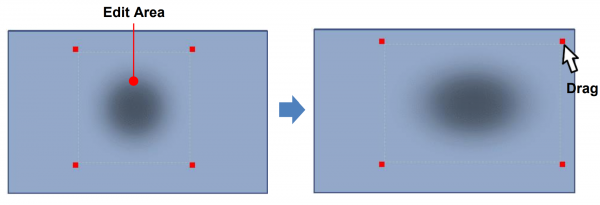
Adjust the hotspot area
- Click Previewto view the mask effect on projection, then click Preview again to return to the test pattern.
- To clear the hotspot point on the screen, at the function tab, click RESET
VII. Color Uniformity
Color uniformity is to adjust the uniformity gain of projection image to improve and fine tune the uniformity performance.
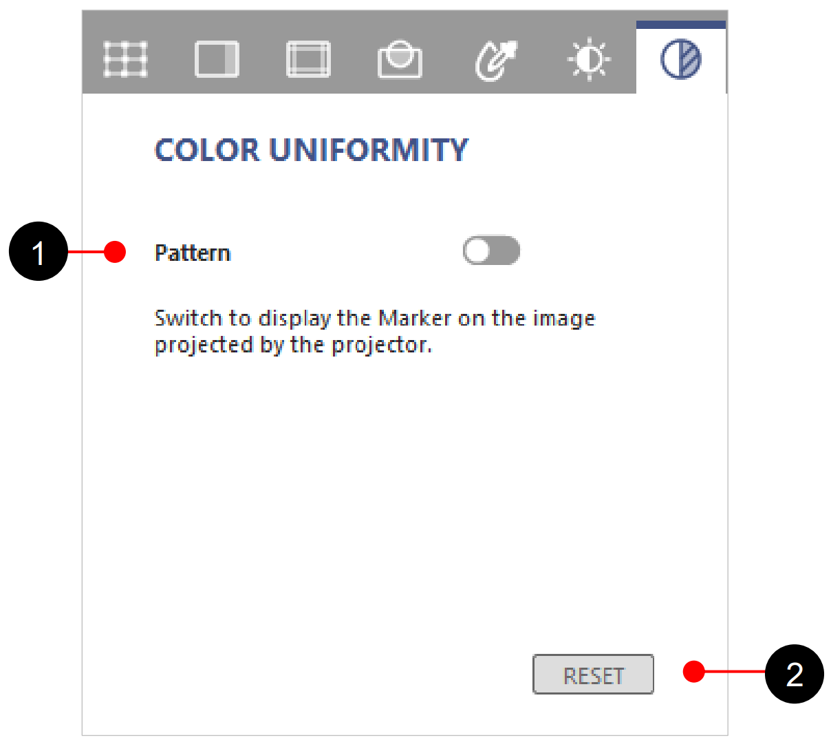
Function tab – Color Uniformity
| No. | Function | Description |
| 1 | Pattern | Pop-up the color uniformity gain control page, there are 63 (9×7) positions for uniformity gain control. |
| 2 | Reset | Click to reset the uniformity gain to project default setting. |
Complete following steps to adjust the color uniformity:
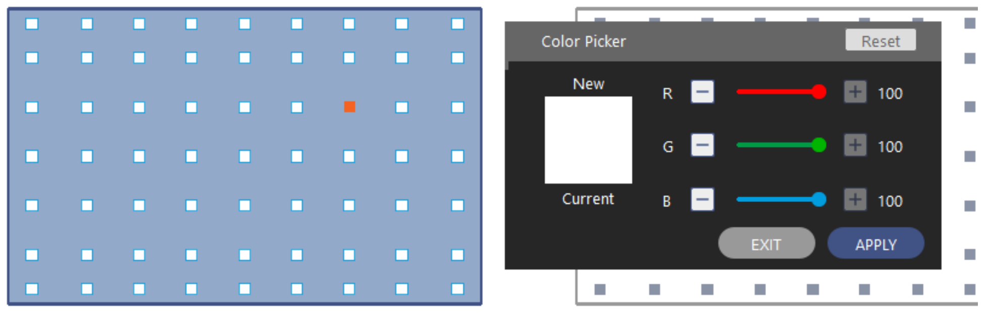
- Switch to the Color Uniformity function tab. The test pattern automatically changes to the image of Color Uniformity control points.
- Choose one of 63 control points and double click to get uniform color display.

Color Picker
- Enter the RGB value or drag the slider to set the color of the selected area.
- Click APPLY on the Color Picker dialog to apply the value to the selected area.
- To clear the color uniformity settings, at the function tab, click RESET.
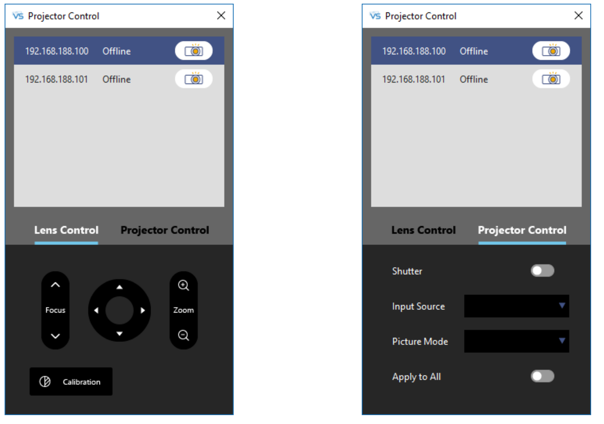
VIII. Projector Control
Visual Suite provides some basic projector control functions, such as lens adjustment(shift, zoom and focus), shutter and input source selection. You can find these functions at top toolbar.